Using and Driving a Solenoid
 A solenoid is a coil that pulls (or
pushes) a metal rod called
a plunger when current flows through it. There are many kinds of
solenoids: pull and push types, with and without springs (to push back
the plunger when current no longer flows), with and without latches,
etc. The main advantage of solenoids over motors is that they can
effect a linear motion using a compact mechanism with no gears. On the
negative side, solenoids have a very short stroke (the length of
movement of the plunger).
A solenoid is a coil that pulls (or
pushes) a metal rod called
a plunger when current flows through it. There are many kinds of
solenoids: pull and push types, with and without springs (to push back
the plunger when current no longer flows), with and without latches,
etc. The main advantage of solenoids over motors is that they can
effect a linear motion using a compact mechanism with no gears. On the
negative side, solenoids have a very short stroke (the length of
movement of the plunger).
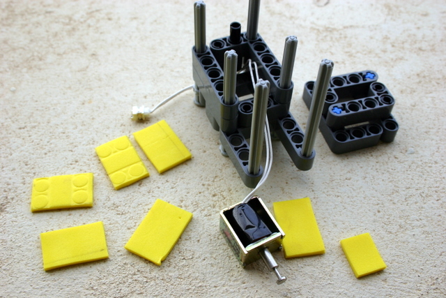
In this project I tried to utilize a small solenoid that I
removed from an old Iomega 100MB Zip drive. The solenoid itself, which
you can see in the picture below, is smaller than 2x3x3 Lego units. It
is a
pull-type solenoid with no spring to push the plunger back out. The
plunger ends with a wide disk that is designed to pull something with
it. The resistance of the coil is only 3.6Ohm, so if you connect it to
a 9V supply, it will draw 2.5A (after a ramp-up period).
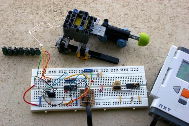
The next few paragraphs explain how to integrate the solenoid
into a Technic structure, how to use it to fire the Technic cannon (a
spring-loaded Technic part that fires a little missile with a foam head
when you pull back a trigger axle), and how to drive the solenoid from
the NXT, either using a motor port (really easy) or a sensor port (more
challenging).
A video
shows the sensor-port activated solenoid in action: the mechanism
charges for 15 seconds and then fires. You can of course wait for some
external event before firing, like detecting a sound or a nearby object.
Warning: connecting your NXT to any home-made
gizmo (like the
one described here) can damage it. Beware.
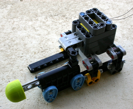
Integrating the Solenoid into a Technic Construction
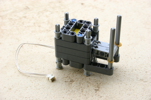
The first step was to integrate the solenoid into a Technic
contruction. I ended up encasing it in a Technic box with a 2x3x3
cavity with a slot in front for the plunger. To make the fit tight, I
used cut-to-size pieces of thin craft foam (about 1mm).
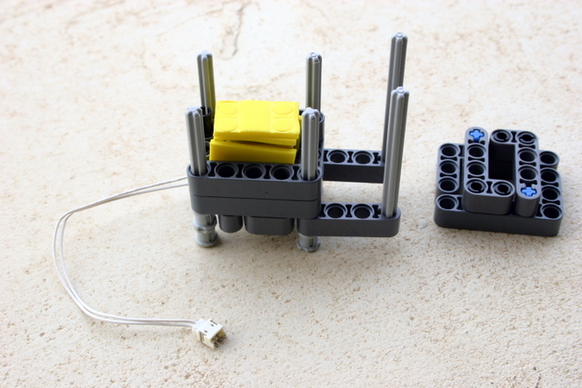
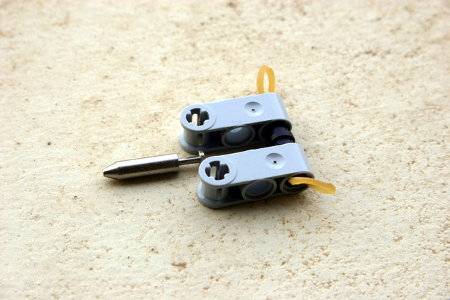
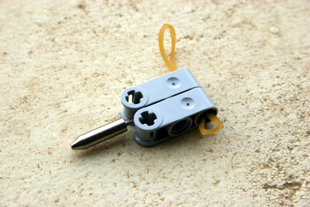
Fortunately, the little disk at the end of the plunger fits
very nicely
into the slots in the axle joiners, so I used them as a Technic
extension of the plunger. I initially used a rubber band to pull back
the plunger (but see below for a better idea).
The useful travel of the plunger is about 1/2 Lego unit. If
you pull it by more that this, the solenoid might not be able to pull
it back. This is not much. Here is the whole thing together.
An alternative construction might be to encase the solenoid in
two 2x3 bricks stacked one on top of the other and hollowed out. This
would be much more compact than the Technic box that I constructed. You
would need to close off the bottom with a 2x3 plate, but the studs of
the plate might not leave enough vertical room for the solenoid (but I
didn't try). A potential disadvantage of this costruction is that the
front wall of the bricks might further limit the movement of the
plunger, which is short anyway.
Using the Solenoid/Technic Combination
It took me a while to figure out what this construction is
good for. The stroke of the plunger is short, and to keep the
plunger pulled requires a lot of current. These considerations rule out
many potential applications, like activating a pneumatic valve (this is
a common use for solenoids, but this particular solenoid is a poor fit
fot the Lego pneumatic valves).
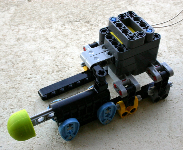
Then I remembered that there is one Technic mechanism that is
activated by a small momentary movement: the Technic competition
cannon. As it turns out, the solenoid is perfect for
triggering the Technic cannon.
The one difficulty is mounting the cannon so that the solenoid
can trigger it. I had to offset the solenoid mechanim and the cannon by
half a stud in two dimentions, which is what the cams and the "Technic
Axle Joiners Perpendicular Double Split" are used for. The plunger
assembly pulls a "Technic Pole Reverser Handle" that is mounted on the
cannon's triger axle; the handle is not pushed all the way on the
trigger, but there is a gap of about 1/4 of a unit to keep the plunger
horizontal.
Driving the Solenoid
I connected the solenoid to one of the NXT's motor ports (more
specifically to port A) in series with 2 resistors of 1Ohm nominal
resistance each. The resistors were a little higher than specified,
about
2.5Ohm total. I am not sure that they are necessary, but I felt that
this would be safer than connecting a coil with only 3.6Ohm resistance
directly to the motor port. With the resistors the total resistance is
more than 6Ohm, which limits the port's current to less than 1.5A.
I activated the solenoid by turning on Port A at 100%
power for 10ms. This activates the solenoid reliably and fires the
cannon. To understand what exactly is going on, I measured
the port voltages and the current through the solenoid using an
oscilloscope. The graphs below show the results.
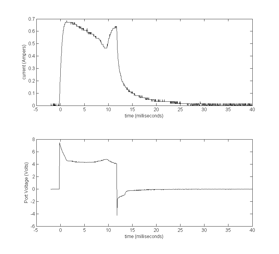
As expected, the port voltage goes high almost immediately.
The current ramps up because of the inductance of the solenoid's coil.
This causes the port's voltage to drop from about 7V (The NXT used
rechargeable batteries) to less than 5V. Then the current continues to
drop. I am not sure why, perhaps because of the movement of the
plunger. At some point the current climbs
again, perhaps the result of the plunger reaching the end of its
stroke. When the NXT powers off the port, the current ramps down
gradually (again
due to the inductance), which causes a short negative-voltage spike
until the protection diode in the NXT starts conducting. The protection
diode stops conducting when the votage across it drops to below the
diode's threshold, so the low negative voltage in the port lingers for
a while longer.
Using a Capacitor to Power the Solenoid from a Sensor Port
The next driving method uses a sensor port rather than a motor
port. This leaves the motor ports available, well, for motors. The
circuit is an I2C circuit so it can be used on the same port with other
I2C sensors.
The key here is to slowly charge a large capacitor using the
4.3V supply, and then to discharge it all at once through the solenoid
to activate it. To work, the capacitor need to
have (1) high enough capacitance to store enough charge to activate the
solenoid, and (2) low enough internal resistance (called ESR) to
discharge quickly enough to generate a large current through the
solenoid.
The graphs above show roughtly how large the capacitor needs
to be.
The
activation above uses about 500mA for 10ms. This is equivalent to 0.005
coulomb of charge. At 5V, a capacitor would need to be 1mF (1000uF) to
store that much charge. In reality, the capacitor would need to be
larger, because as the capacitor discharges, the voltage across it
drops, reducing the current through the solenoid. So the capacitor
would need to be several times larger.
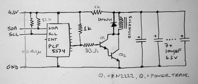
After a few experiments I was able to get it to work. The
circuit slowly charges seven 1000uF capacitors. A PCF8574 (actually a
PCF8574A, which has a different I2C address) controls a darlington
transistor configuration. Most of the time, the transistors should be
off, which essentially disconnects the solenoid from the circuit. When
the 8574 turns its outputs on, this turns on the darlington
pair and discharges the capacitors through the solenoid, thereby
activating it.
The capacitors are charged through a 1k resistor, which gives
a 7-seconds RC constant. In the program, I let it charge for 15 seconds
before firing, to let the capacitors charge more fully. You can use a
larger value resistor, say 2.2k, to reduce the maximum charging
current, but this will also slow down the charging phase.
Turning on the transistors requires a bit of care. The 8574
can only supply about 100uA of current, which is not enough to turn the
darlington pair on completely. The effect that you see on the scope is
(1) the pin of the 8574 does not reach anywhere near Vcc, and (2) the
voltage of the capacitors drops down linearly, which means that the
switching transistor is only allowing constant current to flow, which
in turn means that it is not saturated. I solved this by adding a 1K
pullup resistor to the darlington base, which provides enough base
current to energize the solenoid. But this is an awkward solution since
the pullup resistor is now drawing about 5mA when the capacitors are
charging. Not terrible but still a waste.
An I2C chip like the MCP23008 that can provide 25mA (in any
direction, to Vcc or to ground) would be a better choice here (but I
don't have one right now).
I used a discrete darlington pair (with a high-voltage power
transistor that I removed from an old PC power supply, but you can use
any NPN transistor that can pass 2A or so). To activate several
solenoids, a chip like the ULN2003 or the ULN2803 would be a better
choice: these chips combine 7 or 8 darlington pairs that can pass 500mA
each in a small package. (Thanks to Michael Gasperi who suggested the
use of the ULN2003 for a stepper controller for the NXT.)
If you build a similar circuit, build first a simple test circuit to
make sure that your capacitor(s) have enough capacitance and low-enough
ESR. Charge them slowly through a resistor, and then discharge them
through the solenoid, with a reverse-biased diode in parallel with the
solenoid.
© 2007, Sivan Toledo